
Instrument Performance
2023-07-07
CSST Instrument Performance
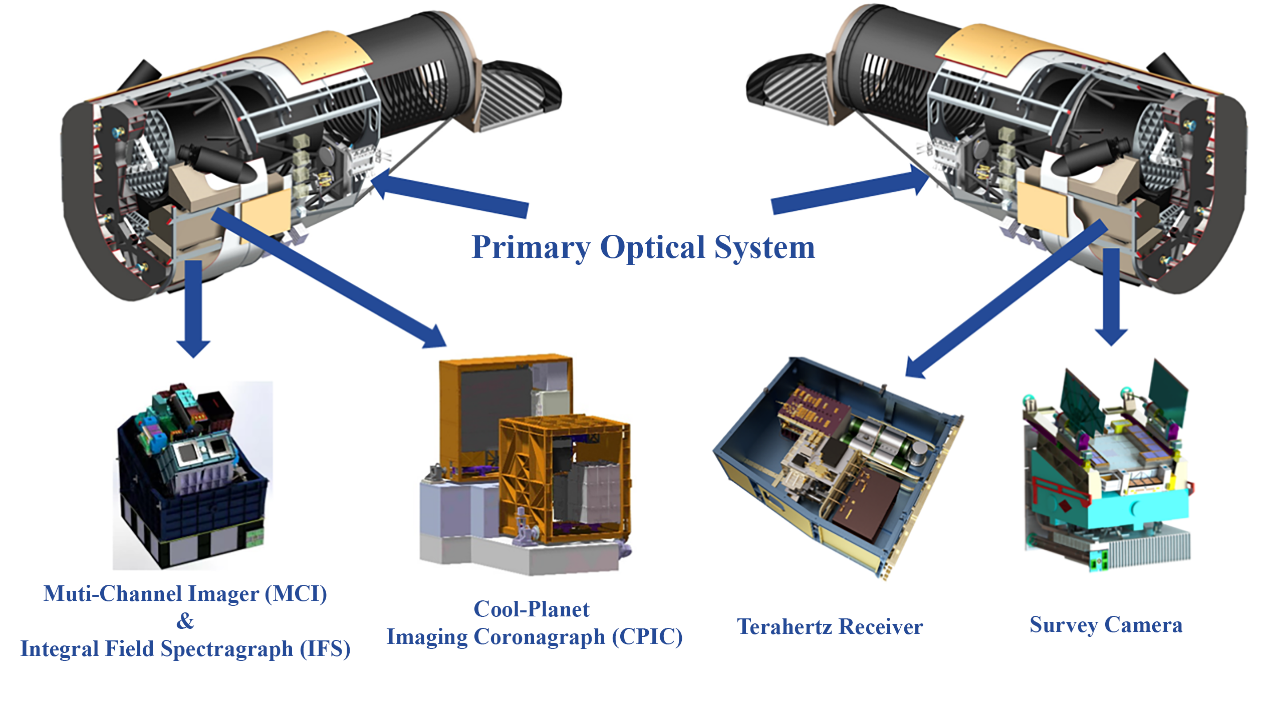
The primary optical system:
The primary optical system is an off-axis three-mirror optical system, possessing exceptional performance in both large field of view and high image quality. A flat mirror is incorporated near the system's exit pupil to fold the optical path, utilizing this flat mirror to simultaneously switch the back-end modules, focus, and stabilize the image. The primary optical system circumvents the mutual obstruction of the mirrors during light propagation by offsetting the aperture, achieving off-axis unobstructed imaging.
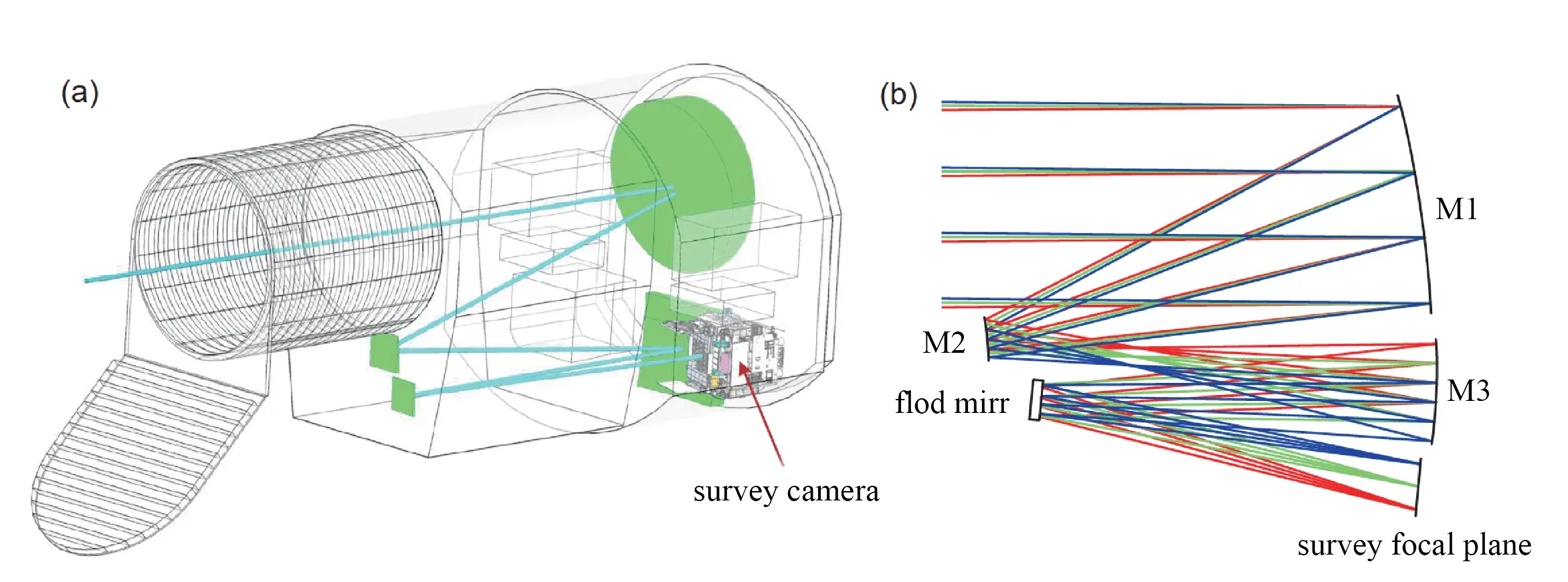
Illustration of the survey camera inside the CSST optical system (a) and Cook-type off-axis three-mirror anastigmatic optical design (b)

HST PSF calculated using Tiny Tim ((a), pixel size 0.049″), CSST optics designed PSF (REE80=0.12″) degraded to REE80=0.145″ ((b), pixel
size 0.074″; optical model is provided by Changchun Institute of Optics, Fine Mechanics and Physics, Chinese Academy of Sciences), and designed PSFof a Euclid-like optical system ((c), pixel size 0.10″, PSF data are provided by Nanjing Institute of Astronomical Optics & Technology, NationalAstronomical Observatories, Chinese Academy of Sciences), all shown in the same stamp size of 6.4″×6.4″
 、
、
Survey Camera:
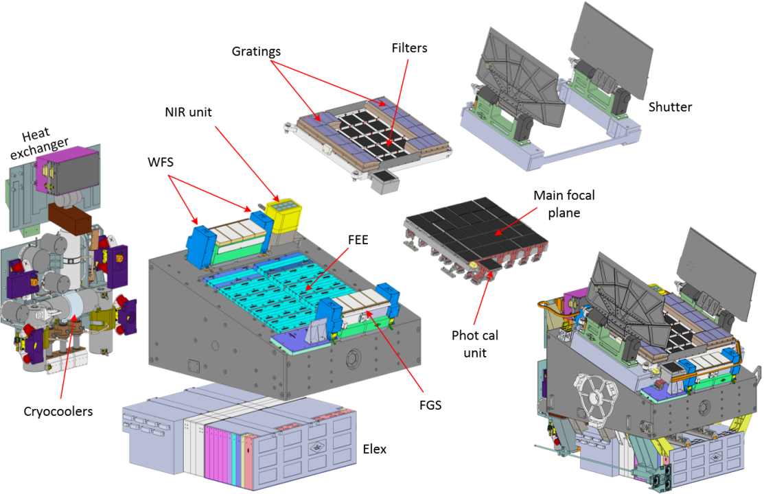
Structure of the Survey Camera
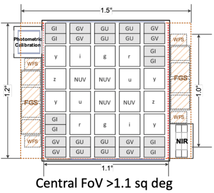
Focal plane arrangement of the CSST survey camera
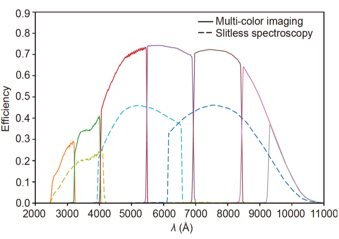
System throughput of CSST survey bands
The survey module is the most important terminal instrument of the multifunctional optical facility in the space station’s optical cabin. It will be used to carry out highly competitive large-area, high-resolution multicolor imaging and seamless spectroscopic survey observations. The survey module consists of a focal plane assembly, a post-optical assembly, a calibration light source assembly, structure and mechanism, thermal control and cooling, and an electrical control box.
The multicolor imaging subsystem covers a wavelength range of 0.255µm to 1.0µm, including at least 6 bands (NUV, u, g, r, i, z, and +y band).
The slitless spectroscopic component is a large-scale mosaic grating dispersion focal plane assembly within the survey module, situated anterior to the telescope’s focal plane, effectuating the spectroscopic dispersion function of astronomical scientific objectives. The seamless spectroscopic component employs a design that shares the focal plane with imaging. 12 gratings are rigidly installed on one side of the focal plane (encompassing 6 CCDs), and 12 gratings are rigidly installed on the other side (encompassing 6 CCDs). The central portion of the focal plane is utilized for imaging surveys, while the lateral portions of the focal plane are utilized for seamless spectroscopic surveys. Both varieties of survey observations can be conducted concurrently.
Muti-Channel Imager (MCI):
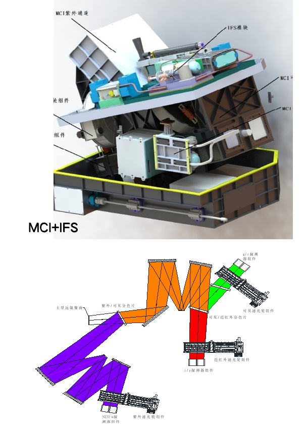
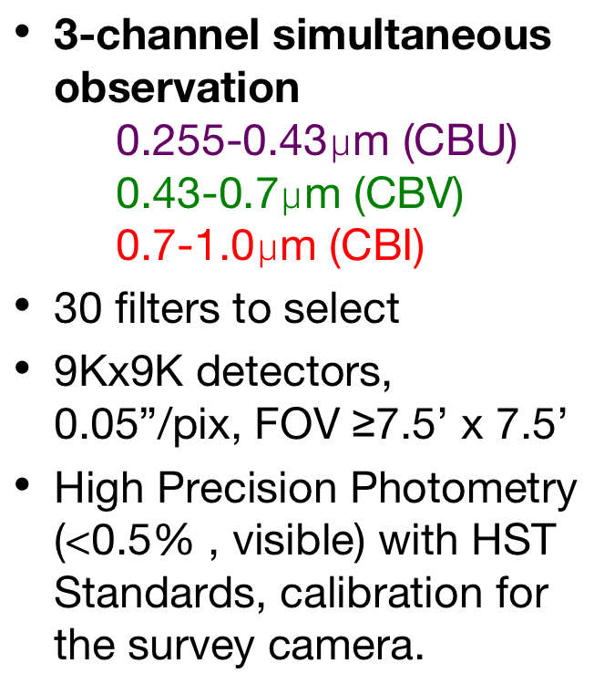
To achieve ultraviolet deep field detection and high-precision photometry with the Multi-Channel Imager (MCI), a two-stage imaging design is employed based on the primary optical imaging. This design involves adjusting the focal length and using a combination of color filters and spectral filters to obtain multiple spectral imaging channels. The detector adopts a 9K*9K 10μm CCD or CMOS device, coupled with a fast shutter mechanism, to achieve high-precision flux calibration and ultra-deep field observations.
Inside the MCI, a calibration source is also installed to monitor the instrument's stability during its operation in orbit. Additionally, the instrument is equipped with a focusing mechanism to adapt to changes in the on-orbit primary optical system's focal plane and match different channel focal planes (primarily due to variations in temperature and gravity fields).
The optical resolution of the main telescope of the optical facility is 0.13", and each pixel in the main survey corresponds to an angular resolution of 0.074". For the Multi-Channel Imager (MCI) to achieve higher angular resolution in its observations, it requires an improvement in pixel angular resolution to 0.05". The MCI is planning to use a detector with a size of 9K×9K pixels, each pixel being 10μm in size. Therefore, the MCI needs to design a relay optics system to magnify the focal length, with a magnification factor of 1.48.
Based on the above parameters, after integrating the relay optics with the main telescope, the combined focal length needs to reach 41,253mm, and the field of view should be 0.128°×0.128° (corresponding to 7.68′×7.68′). The corresponding focal ratio will be F/20.63.
The schematic diagram of the three channels in the Multi-Channel Imager (MCI) consists of one ultraviolet channel and two visible light channels. After the incident light enters the focal plane, it is first directed to the ultraviolet channel using a dichroic beam splitter. Then, both the ultraviolet and visible light channels undergo magnification using an off-axis three-mirror system to achieve a higher focal ratio.The ultraviolet light is directed to the filter group and detector after passing through the off-axis three-mirror system. On the other hand, the visible light goes through a second dichroic beam splitter, separating it into red and green components, which then reach their respective filter groups and detectors.
Cool-Planet Imaging Coronagraph (CPIC):
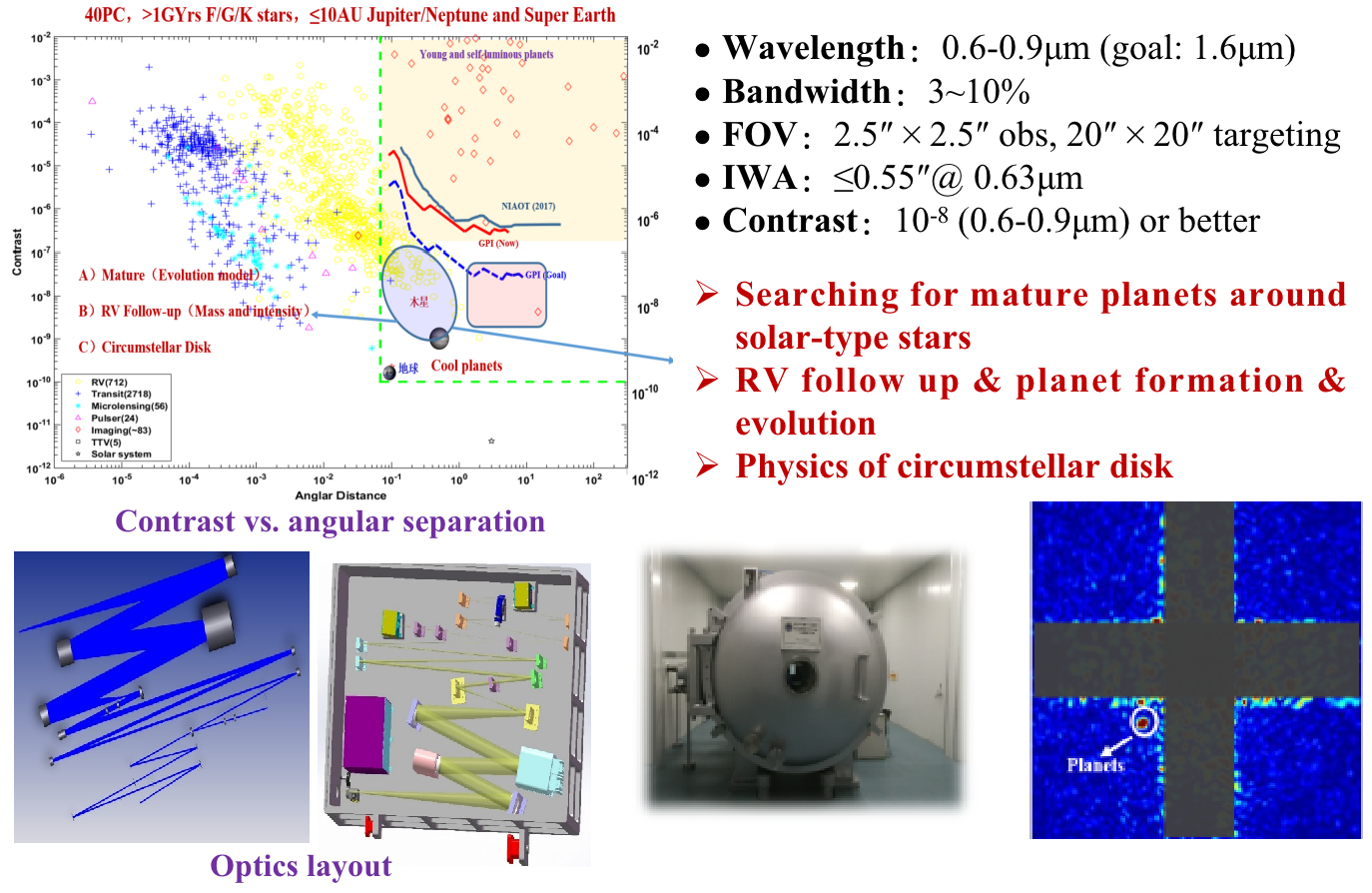
The Coronagraph primarily consists of a diffractive stray light suppressor, high-order wavefront aberration corrector, high-precision stabilization system, laser calibration components, high-precision wavefront sensor, visible light, and near-infrared imaging cameras, among others. It possesses five main functions, including ultra-high contrast measurement, high-precision stabilization, wavefront aberration closed-loop correction, ultra-high contrast self-calibration, and astronomical scientific observation.
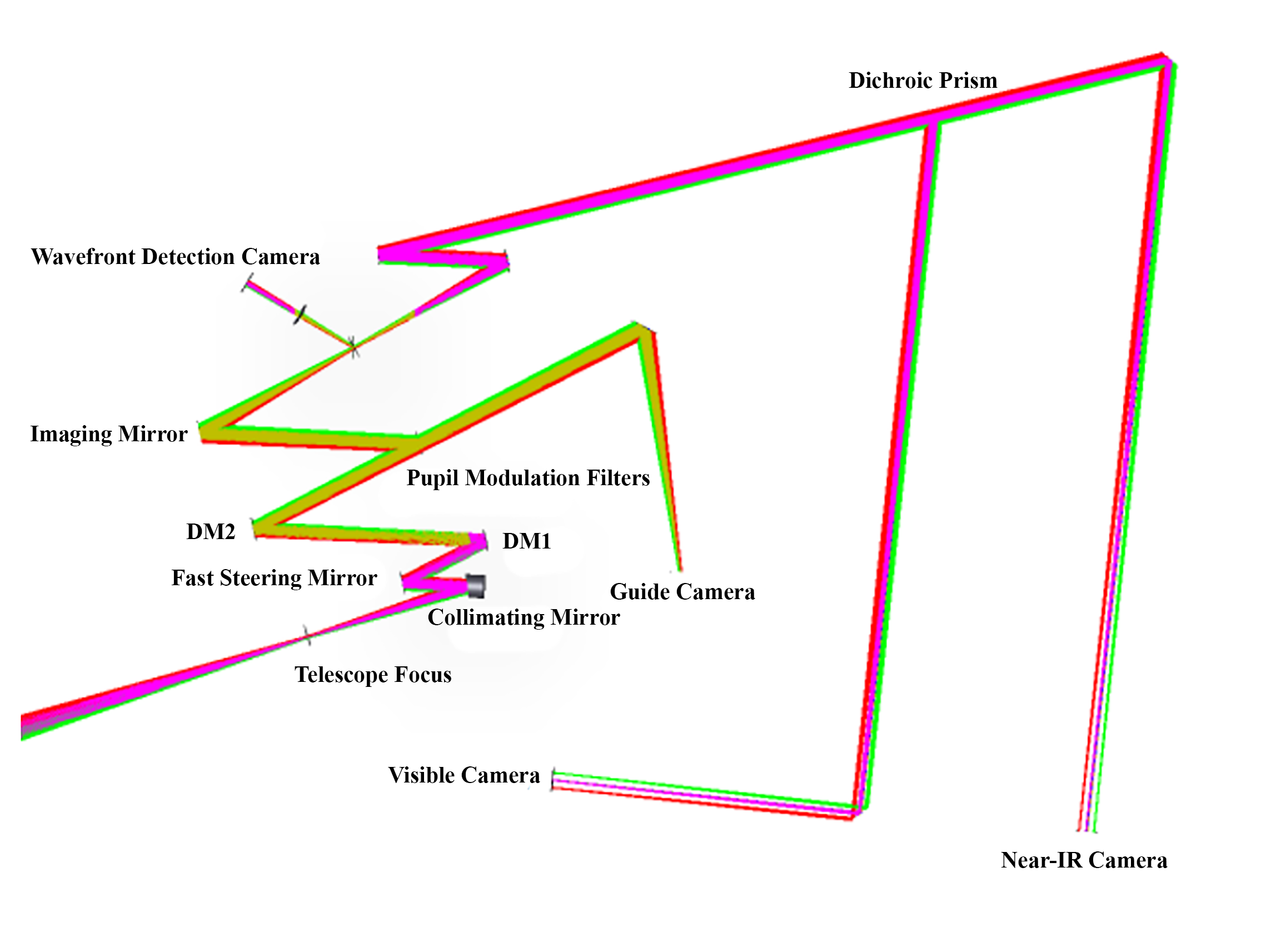
Coronagraph Optical Path Diagram
The telescope reflects light through a three-in-one mirror to the Exoplanet Coronagraph Instrument system and forms an image at the telescope focus. Collimating mirror 1 collimates the light and reflects it successively to the fast steering mirror and two sets of thousand-element deformable mirrors. The beam splitter behind deformable mirror 2 splits the light into two beams: one transmitted beam forms the guide star path and is guided into the guide camera (field of view 20″ x 20″) by imaging mirror 3, while the other reflected beam undergoes subsequent wavefront detection and scientific imaging (field of view 10″ x 10″). The reflected light passes through Pupil Modulation Filters, performing amplitude modulation and phase correction of the pupil energy, respectively.At the focus of imaging mirror 1, a beam splitter is placed for spectral splitting: one beam of light forms the wavefront detection camera path, achieving wavefront detection by introducing a collimating lens and micro-lens array. The other beam of light forms the near-infrared camera path, using collimating mirror 2 and imaging mirror 2 in conjunction, and realizes observations in the corresponding working wavelength bands through a Dichroic prism in front of the visible/infrared detector, combined with a filter wheel.
Integrated Field Spectrometer(IFS):
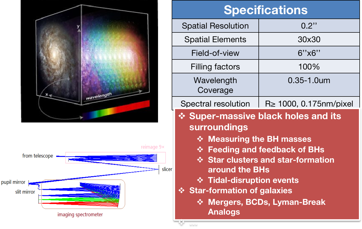
The Integral Field Spectrometer (IFS) is an instrument that covers the entire optical wavelength range and has a spatial resolution up to 0.2 arcseconds. It is used for fine imaging and spectroscopic observations of extended astronomical objects in the universe. Its main technical parameters include:
(1) Field of View Area: The image slicer uses no fewer than 30 image segments (actually designed as 32 segments), with a unit resolution of 0.2 arcseconds. Therefore, the field of view area is greater than 6.0×6.0 arcseconds.
(2) Spatial Resolution of Segmentation Units: To achieve scientific objectives such as studying the central black hole in galaxies and star formation, and to showcase the advantages of space observations and the characteristics of the space station IFS, there are clear requirements for spatial resolution up to 0.2 arcseconds.
(3) Wavelength Coverage Range: 0.35-1.0 μm, covering the ultraviolet, visible, and near-infrared spectra.
(4) Spectral Resolution: The spectral resolution is set to R=1000 at the shortest wavelength (0.35 μm).
(5) Instrument Efficiency: The spectral instrument achieves an efficiency of ≥40% in the wavelength range of 0.42-0.55 μm and above 0.61-0.82 μm, excluding the main optical instrument and including only the IFS optics and detector components.
Terahertz Receiver:
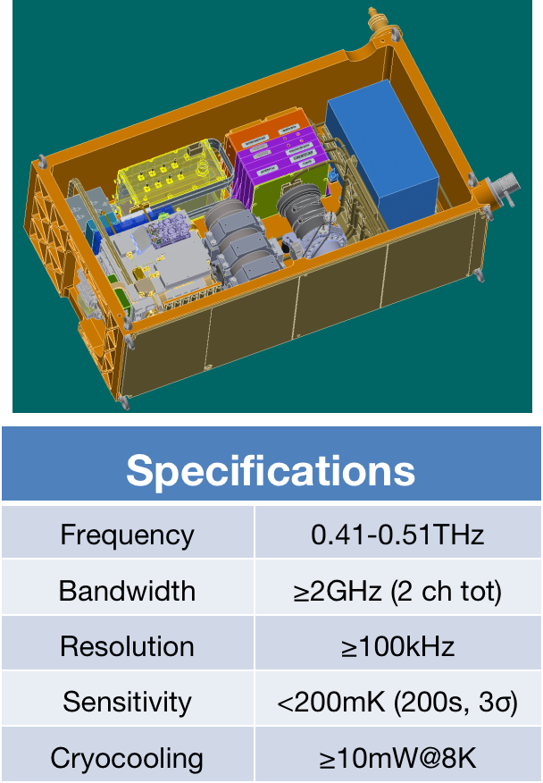

The Terahertz Receiver is a high-sensitivity spectral observation device composed of a superconducting receiver working in the frequency range of 0.41-0.51 THz. It can be used for high velocity resolution and high sensitivity spectral line observations of interstellar medium. Its main technical parameters include:
(1) Reference Radio Frequency Range : 0.41-0.51 THz
(2) Instantaneous Bandwidth : ≥2 GHz
(3) Frequency Resolution : ≥100 kHz
(4) Observational Sensitivity :≤200mK (3σ, with a bandwidth of 100 kHz and an integration time of 200s).
(5) Beam Width : ≤100''